An engineering approach to reducing the risks of fire and explosion hazards and to avoid direct impacts is to have adequate separation distances between hazard sources and vulnerable groups (people, equipment and structure). This requires due consideration be given to process module arrangement, occupied areas, hazardous area classification, fire zones, structural and machinery protection, and offloading operations.
Continue reading or Download a Free PDF Copy
“Where space is at a premium, as it is on FLNG vessels, one of the challenging tasks in topsides layout is to design the separation distances necessary for protection of people and critical systems.”.
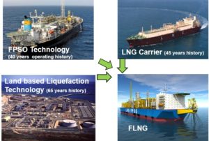
Floating LNG (FLNG) installations for terminal and production applications feature topsides that include process and non-process equipment arrangement, with additional sources of risk as compared to LNG carriers. A typical FLNG unit comprises of a hull with cargo storage, machinery spaces in the bow and stern, cryogenic liquid offloading system and an accommodation unit either at fully forward or fully aft depending on the layout of process modules, wind direction and vessel’s weather-vaning capability. Process and utility modules are on the main deck with a pipe rack interconnecting piping between modules. The limited deck space results in several areas with significant congestion, including piping network, turret and riser area, and process equipment. The design may also include provision for primary and secondary access and escape routes as well as temporary refuge.

Contending with risk
Topsides equipment introduce the possibility that a methane vapor cloud could form on the deck. In an open deck space, there is less likelihood that a methane vapor cloud could form which would generate large overpressures, if ignited. However, the congestion on the deck of an FLNG vessel can generate sufficient turbulence to give rise to higher overpressure and increased explosion risk. In such a case, smaller equipment also is subjected to higher drag loads.
As methane is lighter than air, its dispersion is driven by buoyancy. It is important to note that for LNG leaks, the cold methane vapor initially is moved about by gravity. Buoyancy may take over dispersion faster due to dilution by obstacles. A concentration reaching the Lower Flammability Limit (LFL) can be achieved while the cloud is still heavy. In cases where propane is used as a refrigerant, loss of containment leads to heavy propane vapor settling at bottom levels.
An engineering approach to reducing the risks of fire and explosion hazards and to avoid direct impacts is to have adequate separation distances with due consideration to occupied areas, hazardous area classification, structural and machinery protection, and offloading operations. In many cases, proper separation distances prevent ignition and can also mitigate the effects of an explosion or a fire, should one occur. While there are industry codes and standards that address requirements for other land and floating structures, such as NFPA 59A, IGC Code, and IEC 60079, these might not be adequate or directly applicable to FLNG topsides. Thus, risk-based approaches and Computational Fluid Dynamics (CFD) are being applied to better understand the accident scenarios and evaluate design options.
Managing separation distances
“The primary objective is to prevent injury to personnel onboard and to create a safe means of escape available during an emergency. “.
Separation distances play a vital role in reducing risks and have direct impact on performance requirements of protection systems at various levels. Effective separation distance management leads to:
• Reduced potential for flammable and cryogenic liquids and gaseous hydrocarbons accumulation that can lead to hazardous situations;
• Reduced probability of ignition;
• Separation of non-hazardous and hazardous areas;
• Reduced escalation of consequences of fires and explosions;
• A means for effective emergency response activities;
• Integrity of escape and evacuation arrangements.
Continue reading or Download a Free PDF Copy
Occupied areas
The separation distance between occupied areas, such as accommodation, temporary refuge, work areas and evacuation routes, and process modules and offloading lines, includes a thermal radiation protection zone and a flammable vapor dispersion zone. In the former, occupied area is large enough that thermal flux levels at periphery of the zone do not exceed a certain level in an event of fire. The fire load for exposed personnel is assessed in terms of heat radiation over a certain period. In the latter, occupied area is large enough that in an event of a loss of containment, average concentration of flammable gas with air does not exceed a certain level, usually 0.5 LFL.
API Std 521 provides thermal radiation criteria for establishing separation distances for personnel safety as well as emergency and escape actions. Both planned releases, such as flaring and venting during normal and emergency conditions, and unplanned releases including loss of containment leading to ignition and subsequent fire and/or explosion, should be considered.
“One of the objectives of hazardous area classification is to separate areas that experience different frequencies of occurrence of flammable vapor. This frequency guides the selection of protection equipment to control the ignition sources.”.
Hazardous area classification
The flammable vapor dispersion zone required for electrical apparatus safety is better known as hazardous area classification. Although IEC and API provide prescriptive hazard radii for specific zones, they do not adequately address LNG spill and dispersion scenarios that could occur within the novel configurations of liquefaction modules in offshore environments.
Dispersion studies using either simple models or computational fluid dynamics (CFD) are used as an alternative technique. As a rule of thumb, a 0.5 LFL concentration at a downwind distance with wind speed of 0.5 m/sec is taken as a vapor exclusion zone. An important assumption is the composition of the product and the LFL of that composition. A good practice is to base calculations on 0.5% LFL of a composition rather than prescribed 2.5% (which is used because it represents 0.5% LFL of pure methane). Other factors that affect release rate, like source geometry and process conditions, are also an important part of the equation. Ventilation plays a significant role in calculating hazardous zones as well.
“Physical effects modeling and risk assessments increasingly are being used to allocate and strategically position protection devices in fire zones.”
Fire zones
The separation distances between the process modules, or fire zones, are designed with two primary objectives. The first is physical separation to prevent or reduce fire escalation. The second is to facilitate design and operation of active fire protection systems like gas and fire detectors, and emergency shutdown system.
Structural and Machinery Protection
One of the rule requirements developed by classification societies for building and classifying offshore facilities is the fire integrity of bulkheads separating adjacent spaces. The physical space between bulkhead and protected space is an important consideration in calculating design loads. Other factors like ventilation, penetrations, and deluge systems also play a significant role in assessing fire and explosion loads. The same principle applies to machinery spaces and their compartmentalization.
Offloading operation

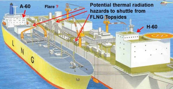
The type of offloading operation used between the FLNG and shuttle tanker and the distance that separates the two units can also influence FLNG topsides arrangement. Risk assessment and Limit State assessment should consider the fire loads from FLNG topsides and offloading operations on the shuttle tanker to determine a recommended vessel-separation distance. Such assessments should also include thermal radiation effects from FLNG flaring as well as accidental fires from process and offloading areas.
Reducing and managing risk
Although separation distances play a major role in reducing risks, the significance of other inherent design practices, active and passive devices and procedural methods should also be recognized in the design process.
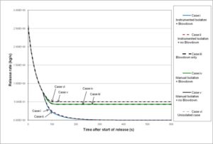
Figure: Release Rates with Manual and Auto Shutdown and Blowdown

“Risk management does not end with design. It is a continuous effort that is applicable through design, construction, installation, commissioning, normal and transient operations, and decommissioning.”.
In making design decisions like separation distances for offshore installations, CFD tools for dispersion, ventilation, explosion and fire assessments continue to overcome the limitations of simple empirical models. Technology and engineering verification tools and methods are mature enough to drive the success of FLNG projects.
References
The paper has been modified from sections of following references (original research paper author is Technical Director with SafeQ Services):
• Das, B. (Jan 2013). Challenges of FLNG Topside Design against Fire and Explosion Loads. LNG Journal. pp 21-25. LNG Journal.
• Das, B. (Dec 2012). Keeping your distance – design measures for FLNG projects to minimize risk. LNG Industry. Issue: Winter 2012, pp 24-27. Palladian Publications.
• Das, B. (Oct 2012). Challenges of FLNG Topside Design against Fire and Explosion Loads. Gastech London 2012.
• Das, B., & Weinberg, M. (Jun 2012). Improving Flammable Mass Estimation for Vapor Cloud Explosion events in QRA. (pp 1218-1227, Vol 50, Issue 5) 2012 Safety Science, Elsevier.
Please leave your comment below.
For questions and suggestions please email to contact@safeqservices.com

